
User Guide


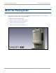


Table Of Contents
- Cambium
- PMP 450 Planning Guide
- Accuracy
- Copyrights
- Restrictions
- License Agreements
- High Risk Materials
- Safety and regulatory information
- Contents
- List of Figures
- List of Tables
- About This Planning Guide
- PMP support website: http://www.cambiumnetworks.com/support
- Cambium main website: http://www.cambiumnetworks.com/
- Sales enquiries: solutions@cambiumnetworks.com
- Email support: support@cambiumnetworks.com
- Cambium Networks
- 3800 Golf Road, Suite 360
- Rolling Meadows, IL 60008
- Chapter 1: Product description
- Chapter 2: Planning considerations
- Regulatory planning
- Network migration planning
- Site planning
- Link planning
- Analyzing the RF Environment
- Selecting Sites for Network Elements
- Diagramming Network Layouts
- Grounding and lightning protection
- Configuration options for TDD synchronization
- Data network planning
- Security planning
- Isolating APs from the Internet
- Managing module access by passwords
- Filtering protocols and ports
- Port Lockdown
- Isolating SMs
- Filtering management through Ethernet
- Allowing management from only specified IP addresses
- Configuring management IP by DHCP
- Planning for airlink security
- Planning for RF Telnet Access Control
- Planning for RADIUS integration
- Planning for SNMP security
- Ordering components
- Chapter 3: Legal information
- Cambium Networks end user license agreement
- Acceptance of this agreement
- Definitions
- Grant of license
- Conditions of use
- Title and restrictions
- Confidentiality
- Right to use Cambium’s name
- Transfer
- Updates
- Maintenance
- Disclaimer
- Limitation of liability
- U.S. government
- Term of license
- Governing law
- Assignment
- Survival of provisions
- Entire agreement
- Third party software
- Hardware warranty
- Limit of liability
- Cambium Networks end user license agreement
- Chapter 4: Reference information

PMP 450 Planning Guide List of Figures
pmp-0047 (December 2012)
vii
List of Figures
Figure 1 Line Of Sight Diagram .............................................................................................................................................1-3
Figure 2 AP, Radio unit ..........................................................................................................................................................1-5
Figure 3 AP, antenna ..............................................................................................................................................................1-5
Figure 4 AP interfaces ............................................................................................................................................................1-6
Figure 5 AP diagnostic LEDs, viewed from unit front ...........................................................................................................1-7
Figure 6 PMP 450 Series SM .................................................................................................................................................1-9
Figure 7 SM interfaces ..........................................................................................................................................................1-10
Figure 8 SM diagnostic LEDs, viewed from unit front ........................................................................................................1-11
Figure 9 TDD frame division................................................................................................................................................1-14
Figure 10 AP web-based management screenshot ................................................................................................................1-19
Figure 11 Determinants in Rx signal level ............................................................................................................................2-17
Figure 12 Example layout of 16 Access Point sectors (ABCD), 90 degree sectors ..............................................................2-21
Figure 13 Example layout of 16 Access Point sectors (ABC), 60 degree sectors.................................................................2-22
Figure 14 OFDM Frame Calculator tab ................................................................................................................................2-24
Figure 15 Variables for calculating angle of elevation (and depression) ..............................................................................2-28
Figure 16 Rolling sphere method to determine the lightning protection zones ....................................................................2-32
Figure 17 Grounding cable minimum bend radius and angle ...............................................................................................2-34
Figure 18 Grounding and lightning protection on mast or tower ..........................................................................................2-35
Figure 19 Grounding and lightning protection on wall .........................................................................................................2-36
Figure 20 Grounding and lightning protection on building ..................................................................................................2-37
Figure 21 Grounding and lightning protection inside high building .....................................................................................2-38
Figure 22 One unsynchronized AP in cluster resulting in self-interference .........................................................................2-40
Figure 23 GPS timing throughout the network .....................................................................................................................2-41
Figure 24 Cambium network management domain ..............................................................................................................2-43
Figure 25 Example of IP address in Class B subnet ..............................................................................................................2-45
Figure 26 Categorical protocol filtering ...............................................................................................................................2-56
Figure 27 AP DFS Status ......................................................................................................................................................4-14