
User's Guide
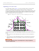

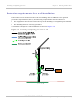
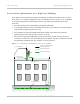
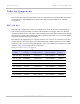
Table Of Contents
- PTP 250 User Guide
- Safety and regulatory information
- Contents
- List of Figures
- List of Tables
- About This User Guide
- Chapter 1: Product description
- Chapter 2: Planning considerations
- Chapter 3: Legal information
- Chapter 4: Reference information
- Chapter 5: Installation
- Chapter 6: Configuration and alignment
- Chapter 7: Operation
- Chapter 8: Troubleshooting
- Testing link end hardware
- Testing when PoE LEDs do not illuminate correctly
- Testing after a lightning strike
- Test flowcharts
- AC LED is off
- AC LED is flashing
- PORT LED is off
- PORT LED is flashing
- Test Ethernet packet errors reported by ODU
- Test Ethernet packet errors reported by managed switch or router
- Test ping packet loss
- Test resistance in the ODU cable
- Testing the radio link
- Testing link end hardware
- Glossary

Grounding and lightning protection Chapter 2: Planning considerations
2-18
UNDER DEVELOPMENT
phn-2182_003v004 (Oct 2011)
Figure 2-2 Grounding cable minimum bend radius and angle
Radius not less
than 203 mm (8 in)
Angle not less
than 90°
ODU requirements
The following ODU protection requirements must be implemented:
• The ODU must be grounded to the supporting structure.
Protection requirements for a mast or tower installation
If the ODU is to be mounted on a metal tower or mast, then in addition to the general
protection requirements (above), the following requirements must be observed:
• The equipment must be lower than the top of the tower or its lightning air terminal.
• The metal tower or mast must be correctly grounded.
• A grounding kit must be installed at the first point of contact between the drop cable
and the tower, near the top.
• A grounding kit must be installed at the bottom of the tower, near the vertical to
horizontal transition point. This grounding kit must be bonded to the tower or tower
ground bus bar (TGB), if installed.
• If the tower is greater than 61 m (200 ft) in height, an additional grounding kit must be
installed at the tower midpoint. Additional ground kits must be installed as necessary
to reduce the distance between ground kits to 61 m (200 ft) or less.
•
In high lightning prone geographical areas, additional ground kits should be installed
at spacing between 15 to 22 m (50 to 75 ft
). This is especially important on towers
taller than 45 m (150 ft).
A schematic example of a mast or tower installation is shown in Figure 2-3.