
User's Guide
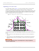
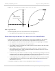

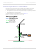
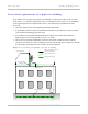
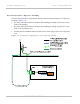
Table Of Contents
- PTP 250 User Guide
- Safety and regulatory information
- Contents
- List of Figures
- List of Tables
- About This User Guide
- Chapter 1: Product description
- Chapter 2: Planning considerations
- Chapter 3: Legal information
- Chapter 4: Reference information
- Chapter 5: Installation
- Chapter 6: Configuration and alignment
- Chapter 7: Operation
- Chapter 8: Troubleshooting
- Testing link end hardware
- Testing when PoE LEDs do not illuminate correctly
- Testing after a lightning strike
- Test flowcharts
- AC LED is off
- AC LED is flashing
- PORT LED is off
- PORT LED is flashing
- Test Ethernet packet errors reported by ODU
- Test Ethernet packet errors reported by managed switch or router
- Test ping packet loss
- Test resistance in the ODU cable
- Testing the radio link
- Testing link end hardware
- Glossary

PTP 250 User Guide Grounding and lightning protection
phn-2182_003v004 (Oct 2011)
UNDER DEVELOPMENT
2-17
General protection requirements
To adequately protect a PTP 250 installation, both ground bonding and transient voltage
surge suppression are required.
Basic requirements
The following basic protection requirements must be implemented:
• The ODU must be in ‘Zone B’ (see Lightning protection zones on
page 2-16).
• A lightning protection unit (LPU) must be installed within 600 mm (24 in) of the point
at which the drop cable enters the building or equipment room.
• The drop cable must be bonded to the supporting structure in order to prevent
lightning creating a potential between the structure and cable, which could cause
arcing, resulting in fire risk and damage to equipment.
• The drop cable must be grounded at the building entry point.
• The drop cable must not be laid alongside a lightning air terminal.
• All grounding cables must be a minimum size of 10 mm
2
csa (8AWG), preferably 16
mm
2
csa (6AWG), or 25 mm
2
csa (4AWG).
Grounding cable requirements
When routing, fastening and connecting grounding cables, the following requirements
must be implemented:
• Grounding conductors must be run as short, straight, and smoothly as possible, with
the fewest possible number of bends and curves.
• Grounding cables must not be installed with drip loops.
• All bends must have a minimum radius of 203 mm (8 in) and a minimum angle of 90°
(Figure 2-2). A diagonal run is p
referable to a bend, even though it does not follow the
contour or run parallel to the supporting structure.
• All bends, curves and connections must be routed towards the grounding electrode
system, ground rod, or ground bar.
• Grounding conductors must be securely fastened.
• Braided grounding conductors must not be used.
• Approved bonding techniques must be used for the connection of dissimilar metals.