
User's Guide
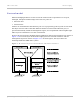
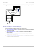

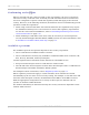
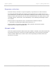
Table Of Contents
- PTP 250 User Guide
- Safety and regulatory information
- Contents
- List of Figures
- List of Tables
- About This User Guide
- Chapter 1: Product description
- Chapter 2: Planning considerations
- Chapter 3: Legal information
- Chapter 4: Reference information
- Chapter 5: Installation
- Chapter 6: Configuration and alignment
- Chapter 7: Operation
- Chapter 8: Troubleshooting
- Testing link end hardware
- Testing when PoE LEDs do not illuminate correctly
- Testing after a lightning strike
- Test flowcharts
- AC LED is off
- AC LED is flashing
- PORT LED is off
- PORT LED is flashing
- Test Ethernet packet errors reported by ODU
- Test Ethernet packet errors reported by managed switch or router
- Test ping packet loss
- Test resistance in the ODU cable
- Testing the radio link
- Testing link end hardware
- Glossary

PTP 250 User Guide Ethernet bridging
phn-2182_003v004 (Oct 2011)
UNDER DEVELOPMENT
1-25
Protocol model
Ethernet bridging behavior at each end of the wireless link is equivalent to a two-port,
managed, transparent MAC bridge where the two ports are:
• Ethernet Port
• Wireless Port
Frames are transmitted at the Wireless port over a proprietary point-to-point circuit-mode
link layer between ends of the link. Ethernet frames received at the Ethernet port, or
generated internally within the management agent, are encapsulated within a lightweight
MAC layer for transmission over the wireless link.
Protocol layers involved in bridging between Ethernet and wireless interfaces are shown in
Figure 1-10. Pro
tocol layers involved in bridging between external interfaces and the
management agent are shown in Figure 1-11. In t
hese figures, the layers have the
meanings defined in IEEE 802.1Q-2005.
Figure 1-10 Protocol layers between Ethernet and wireless interfaces