
User's Guide
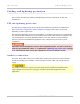
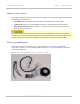
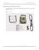


Table Of Contents
- PTP 250 User Guide
- Safety and regulatory information
- Contents
- List of Figures
- List of Tables
- About This User Guide
- Chapter 1: Product description
- Chapter 2: Planning considerations
- Chapter 3: Legal information
- Chapter 4: Reference information
- Chapter 5: Installation
- Chapter 6: Configuration and alignment
- Chapter 7: Operation
- Chapter 8: Troubleshooting
- Testing link end hardware
- Testing when PoE LEDs do not illuminate correctly
- Testing after a lightning strike
- Test flowcharts
- AC LED is off
- AC LED is flashing
- PORT LED is off
- PORT LED is flashing
- Test Ethernet packet errors reported by ODU
- Test Ethernet packet errors reported by managed switch or router
- Test ping packet loss
- Test resistance in the ODU cable
- Testing the radio link
- Testing link end hardware
- Glossary

Cabling and lightning protection Chapter 1: Product description
1-16
UNDER DEVELOPMENT
phn-2182_003v004 (Oct 2011)
Further reading on cabling and lightning protection
For more information on cabling and lightning protection, refer to the following:
• Maximum cable lengths on
page 2-7 gives maximum permitted lengths of interface
cables in PTP 250 installations.
• Grounding and lightning protection on
page 2-15 describes the grounding and
lightning protection requirements of a PTP 250 installation.
• Ordering components on
page 2-24 lists the components required for PTP 250
installations, including cables, connectors, grounding kits and LPUs.
• Installing the drop cable and LPU on page 5-15 de
scribes how to install the drop cable
from the ODU to the LPU and PoE power supply, and to provide grounding for the
installation.
• Installing the PoE power supply on
page 5-29 describes how to prepare the indoor
cables to connect to the network.
• Testing after a lightning strike on
page 8-2 describes testing to be performed after a
PTP 250 installation is struck by lightning.