
User's Guide
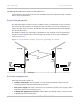
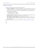
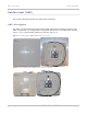
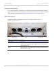

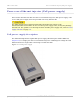


Table Of Contents
- PTP 250 User Guide
- Safety and regulatory information
- Contents
- List of Figures
- List of Tables
- About This User Guide
- Chapter 1: Product description
- Chapter 2: Planning considerations
- Chapter 3: Legal information
- Chapter 4: Reference information
- Chapter 5: Installation
- Chapter 6: Configuration and alignment
- Chapter 7: Operation
- Chapter 8: Troubleshooting
- Testing link end hardware
- Testing when PoE LEDs do not illuminate correctly
- Testing after a lightning strike
- Test flowcharts
- AC LED is off
- AC LED is flashing
- PORT LED is off
- PORT LED is flashing
- Test Ethernet packet errors reported by ODU
- Test Ethernet packet errors reported by managed switch or router
- Test ping packet loss
- Test resistance in the ODU cable
- Testing the radio link
- Testing link end hardware
- Glossary

Power over Ethernet injector (PoE power supply) Chapter 1: Product description
1-10
UNDER DEVELOPMENT
phn-2182_003v004 (Oct 2011)
PoE features
The PoE power supply has the following features:
• Independent power controller (SPEAR™), CPU controller and input (Data) and output
(Data & Power) shielded RJ-45 connectors.
• Supports standard 10/100/1000BaseT Ethernet networks over a standard TIA/EIA-568
Category 5 (or higher) cabling.
• Universal AC Input: 110/220 V, 60/50 Hz.
• Maximum available output power 30 W (nominal output voltage 52 to 56 V DC).
• Underload, overload, short-circuit and under/over voltage port protection.
• Port and AC power LED indicators.
• Standalone or wall mount installation support.
• Coupling rail and slot to allow two or more PoE power supply units to be mounted
together.
PoE power supply interfaces
The PoE power supply interfaces are illustrated in Figure 1-7 and described in Table 1-2
and Table 1-3.
Figu
re 1-7 PoE power supply interfaces