
User's Guide
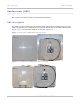

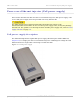


Table Of Contents
- PTP 250 User Guide
- Safety and regulatory information
- Contents
- List of Figures
- List of Tables
- About This User Guide
- Chapter 1: Product description
- Chapter 2: Planning considerations
- Chapter 3: Legal information
- Chapter 4: Reference information
- Chapter 5: Installation
- Chapter 6: Configuration and alignment
- Chapter 7: Operation
- Chapter 8: Troubleshooting
- Testing link end hardware
- Testing when PoE LEDs do not illuminate correctly
- Testing after a lightning strike
- Test flowcharts
- AC LED is off
- AC LED is flashing
- PORT LED is off
- PORT LED is flashing
- Test Ethernet packet errors reported by ODU
- Test Ethernet packet errors reported by managed switch or router
- Test ping packet loss
- Test resistance in the ODU cable
- Testing the radio link
- Testing link end hardware
- Glossary

Overview of the PTP 250 Chapter 1: Product description
1-4
UNDER DEVELOPMENT
phn-2182_003v004 (Oct 2011)
Product variants
The PTP 250 is available in the following product variants:
• FCC/IC or ETSI/RoW: The PTP 250 is available in two regional variants: one is for use
in countries where FCC or IC licensing restrictions apply (FCC/IC), and the other is for
use in ETSI countries or the rest of the world (ETSI/RoW). The regional variants may
operate in the following bands:
o ETSI/RoW: 5.4 GHz or 5.8 GHz.
o FCC/IC: 5.4 GHz or 5.8 GHz only.
• Integrated or Connectorized: Both products are available in either Integrated (with
attached antenna) or Connectorized (without an antenna) variants.
• Link Complete or End Complete: The Link Complete kit consists of two ODUs and
two PoE power supply units. The End Complete kit consists of one ODU and one PoE
power supply unit.
To obtain part numbers for the above variants, refer to Ordering components on
page 2-
24.