
User's Guide
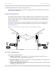
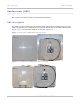
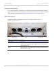

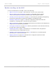
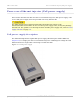


Table Of Contents
- PTP 250 User Guide
- Safety and regulatory information
- Contents
- List of Figures
- List of Tables
- About This User Guide
- Chapter 1: Product description
- Chapter 2: Planning considerations
- Chapter 3: Legal information
- Chapter 4: Reference information
- Chapter 5: Installation
- Chapter 6: Configuration and alignment
- Chapter 7: Operation
- Chapter 8: Troubleshooting
- Testing link end hardware
- Testing when PoE LEDs do not illuminate correctly
- Testing after a lightning strike
- Test flowcharts
- AC LED is off
- AC LED is flashing
- PORT LED is off
- PORT LED is flashing
- Test Ethernet packet errors reported by ODU
- Test Ethernet packet errors reported by managed switch or router
- Test ping packet loss
- Test resistance in the ODU cable
- Testing the radio link
- Testing link end hardware
- Glossary

PTP 250 User Guide Overview of the PTP 250
phn-2182_003v004 (Oct 2011)
UNDER DEVELOPMENT
1-3
Avoiding interference from nearby devices
At initialization, the products monitor the available frequency channels to find a channel
that is clear of interference.
Typical deployment
The PTP 250 bridge consists of a pair of identical units, one deployed at each end of the
link. The radio link operates on a single frequency channel. One unit is configured as a
master and the other as a slave. The master unit takes responsibility for controlling the
link in both directions.
The bridge is aimed at a wide range of applications. One example is an enterprise that
needs to connect together the Local Area Network (LAN) of two or more buildings as
shown in Figure 1-1.
Figu
re 1-1 Typical PTP 250 bridge deployment (grounding not shown)
System components
Each end of the link consists of:
• Outdoor Unit (ODU): An integrated (or connectorized) outdoor transceiver unit
containing all the radio and networking electronics.
• PoE power supply: An indoor connection box containing a mains power supply, status
indicators and network connection port.
• Cabling and lightning protection: CAT5e cables, grounding cables, connectors and
a lightning protection unit (LPU).