
User's Guide
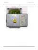
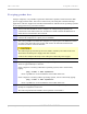
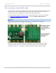
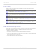


Table Of Contents
- PTP 250 User Guide
- Safety and regulatory information
- Contents
- List of Figures
- List of Tables
- About This User Guide
- Chapter 1: Product description
- Chapter 2: Planning considerations
- Chapter 3: Legal information
- Chapter 4: Reference information
- Chapter 5: Installation
- Chapter 6: Configuration and alignment
- Chapter 7: Operation
- Chapter 8: Troubleshooting
- Testing link end hardware
- Testing when PoE LEDs do not illuminate correctly
- Testing after a lightning strike
- Test flowcharts
- AC LED is off
- AC LED is flashing
- PORT LED is off
- PORT LED is flashing
- Test Ethernet packet errors reported by ODU
- Test Ethernet packet errors reported by managed switch or router
- Test ping packet loss
- Test resistance in the ODU cable
- Testing the radio link
- Testing link end hardware
- Glossary

Testing link end hardware Chapter 8: Troubleshooting
8-10
UNDER DEVELOPMENT
phn-2182_003v004 (Oct 2011)
Test resistance in the ODU cable
If the above procedures fail to diagnose the issue, there may be a fault in the wiring of the
drop cable that connects the ODU (or LPU) to the PoE. Perform this task to test the
resistances between the RJ45 pins at the PoE end of the ODU cable.
Use the PTP drop cable tester (Figure 8-4) to make te
sting easier. This can be ordered
from http://www.motorola.com/ptp/support
by selecting Order Cable Tester and
completing the order form.
The values printed on the PTP drop cable tester do not apply to the PTP 250.
Figure 8-4 Drop cable tester (front and back views)
Unplug the drop cable from the DATA & POWER OUT port of the PoE power supply.
Connect the drop cable tester to the end of the drop cable. Then, perform the tests
described in Table 8-1. Rec
ord the results in the Result column, if this is helpful.