
User's Guide
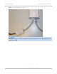


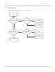
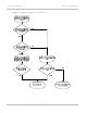
Table Of Contents
- PTP 250 User Guide
- Safety and regulatory information
- Contents
- List of Figures
- List of Tables
- About This User Guide
- Chapter 1: Product description
- Chapter 2: Planning considerations
- Chapter 3: Legal information
- Chapter 4: Reference information
- Chapter 5: Installation
- Chapter 6: Configuration and alignment
- Chapter 7: Operation
- Chapter 8: Troubleshooting
- Testing link end hardware
- Testing when PoE LEDs do not illuminate correctly
- Testing after a lightning strike
- Test flowcharts
- AC LED is off
- AC LED is flashing
- PORT LED is off
- PORT LED is flashing
- Test Ethernet packet errors reported by ODU
- Test Ethernet packet errors reported by managed switch or router
- Test ping packet loss
- Test resistance in the ODU cable
- Testing the radio link
- Testing link end hardware
- Glossary

Testing link end hardware Chapter 8: Troubleshooting
8-6
UNDER DEVELOPMENT
phn-2182_003v004 (Oct 2011)
PORT LED is off
When the PoE power supply is connected to the power supply and the AC LED illuminates,
there should be a 45 second delay, following which the PORT LED should illuminate (green
steady).
If the PORT LED is off, proceed as follows:
1
Check that the RJ45 connection from the DATA IN port of the PoE power supply
to the PC is working.
2
If the PC connection is working, remove and examine the cable that connects
the PoE power supply to the LPU or ODU.
3
Check that the resistances are correct as specified in Test resistance in the ODU
ca
ble on page 8-10.
4
If this test fails, replace or repair the cable that connects the PoE power supply
to the LPU or ODU.
PORT LED is flashing
If the PORT LED is flashing, proceed as follows:
1
Remove and examine the ODU cable from the PoE power supply.
2
Check that the resistances are correct as specified in Test resistance in the ODU
ca
ble on page 8-10.
3
Use the LPU (if installed) to check that power is available on the cable to the
ODU. Access the connections by rotating the LPU lid as shown in Figure 8-3.
S
lacken the lid nut but do not remove it.
4
Test that test point P1 on the LPU PCB corresponds to pin 1 on the RJ45. Repeat
for points P2 to P8.
This test is only valid if both the PoE power supply and the ODU are
disconnected.
5
Check that the PWR LED near the top right of the LPU PCB is illuminated to
indicate power in the Ethernet cable (Figure 8-3).
6
If any test fails, replace or repair the cable that connects the PoE power supply
to the LPU or ODU.