
User's Guide
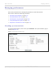
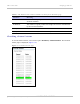
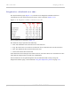

Table Of Contents
- PTP 250 User Guide
- Safety and regulatory information
- Contents
- List of Figures
- List of Tables
- About This User Guide
- Chapter 1: Product description
- Chapter 2: Planning considerations
- Chapter 3: Legal information
- Chapter 4: Reference information
- Chapter 5: Installation
- Chapter 6: Configuration and alignment
- Chapter 7: Operation
- Chapter 8: Troubleshooting
- Testing link end hardware
- Testing when PoE LEDs do not illuminate correctly
- Testing after a lightning strike
- Test flowcharts
- AC LED is off
- AC LED is flashing
- PORT LED is off
- PORT LED is flashing
- Test Ethernet packet errors reported by ODU
- Test Ethernet packet errors reported by managed switch or router
- Test ping packet loss
- Test resistance in the ODU cable
- Testing the radio link
- Testing link end hardware
- Glossary

PTP 250 User Guide Managing link status and alerts
phn-2182_003v004 (Oct 2011)
UNDER DEVELOPMENT
7-15
Managing link status and alerts
This section describes how to manage PTP 250 link status and alerts.
This section contains the following procedures:
• Managing link status on
page 7-15.
• Managing email alerts on page 7-16.
Managing link status
Whenever the Wireless Link Status is not ‘Up’, a yellow warning triangle is displayed on
the navigation bar (Figure 7-7). T
he warning triangle is visible from all web pages. Click
the warning triangle (or menu option Home) to return to the System Summary page and
view the Wireless Link Status. If the warning triangle is replaced by a green square, it
indicates that the Wireless Link Status is ‘Up’ (Figure 7-2).
The
Wireless Link Status values are defined in Table 7-6.
Figure 7-7 Status warning triangle