
User's Guide
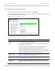

Table Of Contents
- PTP 250 User Guide
- Safety and regulatory information
- Contents
- List of Figures
- List of Tables
- About This User Guide
- Chapter 1: Product description
- Chapter 2: Planning considerations
- Chapter 3: Legal information
- Chapter 4: Reference information
- Chapter 5: Installation
- Chapter 6: Configuration and alignment
- Chapter 7: Operation
- Chapter 8: Troubleshooting
- Testing link end hardware
- Testing when PoE LEDs do not illuminate correctly
- Testing after a lightning strike
- Test flowcharts
- AC LED is off
- AC LED is flashing
- PORT LED is off
- PORT LED is flashing
- Test Ethernet packet errors reported by ODU
- Test Ethernet packet errors reported by managed switch or router
- Test ping packet loss
- Test resistance in the ODU cable
- Testing the radio link
- Testing link end hardware
- Glossary

PTP 250 User Guide Web-based management
phn-2182_003v004 (Oct 2011)
UNDER DEVELOPMENT
7-11
Table 7-5 System Status Wireless attributes
Attribute Meaning
Link Status Current status of the wireless link. A state of ‘Up’ on a green
background indicates that a point-to-point link is established. Any
status on a yellow background indicates that the wireless link is
not established.
Whenever the Link Status is not ‘Up’, a yellow warning triangle is
displayed on the navigation bar. For more information, refer to
Managing link status and alerts on pa
ge 7-15.
MAC Address MAC address of the radio interface of this unit.
Channel Width Width of the wireless channel, either 20 MHz or 40 MHz. This is
set in the Installation Wizard; see Step 2: Wireless configuration
on page 6-16.
Current Channel The channel (MHz) in which this link operates. This is set in the
Installation Wizard; see Step 2: Wireless configuration on
page 6-
16.
Extended Channel The extended channel (MHz). This only applies when Channel
Width is 40 MHz.
Transmit Power The maximum, mean, minimum and latest measurements of
Transmit Power (dBm). See Diagnostics calculated over time on
pag
e 7-23.
Receive Power The maximum, mean, minimum and latest measurements of
Receive Power (dBm). See Diagnostics calculated over time on
page 7-23.
Vector Error The maximum, mean, minimum and latest measurements of
Vector Error (dB). See Diagnostics calculated over time on
page
7-23.
The ve
ctor error measurement compares the In-phase /
Quadrature (IQ) modulation characteristics to an ideal signal to
determine the composite error vector magnitude.
Vector Error is expected to range from -2 dB (NLOS link
operating at sensitivity limit on BPSK 0.50) to –27 dB (short LOS
link running 64QAM 0.83). These are approximate values.