
User's Guide
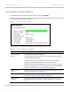

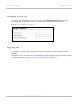
Table Of Contents
- PTP 250 User Guide
- Safety and regulatory information
- Contents
- List of Figures
- List of Tables
- About This User Guide
- Chapter 1: Product description
- Chapter 2: Planning considerations
- Chapter 3: Legal information
- Chapter 4: Reference information
- Chapter 5: Installation
- Chapter 6: Configuration and alignment
- Chapter 7: Operation
- Chapter 8: Troubleshooting
- Testing link end hardware
- Testing when PoE LEDs do not illuminate correctly
- Testing after a lightning strike
- Test flowcharts
- AC LED is off
- AC LED is flashing
- PORT LED is off
- PORT LED is flashing
- Test Ethernet packet errors reported by ODU
- Test Ethernet packet errors reported by managed switch or router
- Test ping packet loss
- Test resistance in the ODU cable
- Testing the radio link
- Testing link end hardware
- Glossary

Web-based management Chapter 7: Operation
7-10
UNDER DEVELOPMENT
phn-2182_003v004 (Oct 2011)
Table 7-4 System Status LAN attributes
Attribute Meaning
IP Address Internet protocol (IP) address. The factory default is 169.254.1.1,
but it may be reset in the Installation Wizard; see Step 1: LAN
co
nfiguration on page 6-14.
Network Mask Defines the address range of the connected IP network. The
factory default is 255.255.0.0, but it may be reset in the
Installation Wizard; see Step 1: LAN configuration on pa
ge 6-14.
MAC Address MAC address of the Ethernet LAN port of this unit. This is not
user-configurable.
Link The current status of the Ethernet link. A state of ‘Up’ with a
green background indicates that an Ethernet link is established.
Any status on a yellow background indicates that the Ethernet
link is not established.
Speed The negotiated speed (Mbps) of the Ethernet interface.
Duplex Indicates whether the unit is transmitting data in full duplex or
half duplex mode. Full duplex is expected in normal operation.