
User's Guide
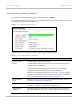

Table Of Contents
- PTP 250 User Guide
- Safety and regulatory information
- Contents
- List of Figures
- List of Tables
- About This User Guide
- Chapter 1: Product description
- Chapter 2: Planning considerations
- Chapter 3: Legal information
- Chapter 4: Reference information
- Chapter 5: Installation
- Chapter 6: Configuration and alignment
- Chapter 7: Operation
- Chapter 8: Troubleshooting
- Testing link end hardware
- Testing when PoE LEDs do not illuminate correctly
- Testing after a lightning strike
- Test flowcharts
- AC LED is off
- AC LED is flashing
- PORT LED is off
- PORT LED is flashing
- Test Ethernet packet errors reported by ODU
- Test Ethernet packet errors reported by managed switch or router
- Test ping packet loss
- Test resistance in the ODU cable
- Testing the radio link
- Testing link end hardware
- Glossary

Web-based management Chapter 7: Operation
7-8
UNDER DEVELOPMENT
phn-2182_003v004 (Oct 2011)
Viewing the system status
To display the System Status page, select menu option Status.
The System Status page (Figure 7-5) gi
ves the user a detailed view of the operation of the
system from both the wireless and network perspectives.
Figure 7-5 System Status page
The page is subdivided into three sections:
• Equipment: This contains the unit’s inventory and identification information.
• LAN: This describes the unit’s network identity and connectivity.
• Wireless: This presents the key wireless metrics, which are displayed as a series of
measurements.
The two ODUs are arranged in a master and slave relationship. The roles of the units in
this relationship are displayed in the page title. The master unit will always have the title ‘-
Master’, and the slave will always have ‘- Slave’ appended to the ‘Systems Status’ page
title.
The status page attributes are defined in Table 7-3
, Table 7-4 and Table 7-5.