
User's Guide
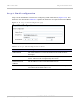
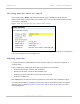

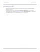
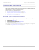
Table Of Contents
- PTP 250 User Guide
- Safety and regulatory information
- Contents
- List of Figures
- List of Tables
- About This User Guide
- Chapter 1: Product description
- Chapter 2: Planning considerations
- Chapter 3: Legal information
- Chapter 4: Reference information
- Chapter 5: Installation
- Chapter 6: Configuration and alignment
- Chapter 7: Operation
- Chapter 8: Troubleshooting
- Testing link end hardware
- Testing when PoE LEDs do not illuminate correctly
- Testing after a lightning strike
- Test flowcharts
- AC LED is off
- AC LED is flashing
- PORT LED is off
- PORT LED is flashing
- Test Ethernet packet errors reported by ODU
- Test Ethernet packet errors reported by managed switch or router
- Test ping packet loss
- Test resistance in the ODU cable
- Testing the radio link
- Testing link end hardware
- Glossary

Aligning antennas Chapter 6: Configuration and alignment
6-28
UNDER DEVELOPMENT
phn-2182_003v004 (Oct 2011)
Graphical alignment
This is the second method that may be used to monitor receive signal level during antenna
alignment.
Select menu option Installation Wizard, Graphical Alignment. The Graphical
Alignment page is displayed (Figure 6-20).
Figu
re 6-20 Graphical Alignment page
The Graphical Alignment page displays the receive power over the last three minutes. This
allows the installer to slowly sweep the antenna during installation and monitor the
variation in signal strength with angular position. The page automatically refreshes every
three seconds.
The page displays the instantaneous signal strength at the top right.