
User's Guide
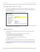


Table Of Contents
- PTP 250 User Guide
- Safety and regulatory information
- Contents
- List of Figures
- List of Tables
- About This User Guide
- Chapter 1: Product description
- Chapter 2: Planning considerations
- Chapter 3: Legal information
- Chapter 4: Reference information
- Chapter 5: Installation
- Chapter 6: Configuration and alignment
- Chapter 7: Operation
- Chapter 8: Troubleshooting
- Testing link end hardware
- Testing when PoE LEDs do not illuminate correctly
- Testing after a lightning strike
- Test flowcharts
- AC LED is off
- AC LED is flashing
- PORT LED is off
- PORT LED is flashing
- Test Ethernet packet errors reported by ODU
- Test Ethernet packet errors reported by managed switch or router
- Test ping packet loss
- Test resistance in the ODU cable
- Testing the radio link
- Testing link end hardware
- Glossary

PTP 250 User Guide Aligning antennas
phn-2182_003v004 (Oct 2011)
UNDER DEVELOPMENT
6-25
To achieve best results, make small incremental changes to elevation and azimuth.
The action of tightening the mounting bolts can alter antenna alignment. This can be
helpful when fine-tuning alignment, but it can also lead to misalignment. To prevent
misalignment, continue to monitor receive signal level during final tightening of the bolts.
To align the antennas, proceed as follows:
1
At each end of the link, adjust the antenna to point at the other end of the link.
This should be done with the aid of a compass.
2
Without moving the master antenna, adjust the elevation and azimuth of the
slave antenna to achieve the highest receive signal level (using one of the
recommended methods in Monitoring received signal level on
page 6-26).
3
Without moving the Slave antenna, adjust the elevation and azimuth of the
Master antenna to achieve the highest receive signal level (using one of the
recommended methods).
4
Repeat steps 2 and 3 as necessary to fine-tune the alignment to find the center of
the beam.
5
When the antennas have been aligned on the center of the beam, verify that the
receive level is within the predicted range (from the installation report). If this is
not the case, go back to step 2.
The current value of receive level can be verified by using Graphical alignment
on page 6-28 o
r by selecting menu option Status and monitoring the Receive
Power attribute on the System Status page.
6
If after repeated attempts to align, the receive level still does not lie within the
predicted range, this may be because the data provided to the prediction tool
(such as PTP LINKPlanner) is inaccurate. For example estimates of path
obstructions, antenna heights or site locations may be inaccurate. Check this
data and update the prediction as necessary.
7
Once the antennas have been aligned correctly, tighten the integrated ODU (or
connectorized antenna) mountings. To ensure that the action of tightening does
not alter antenna alignment, continue to monitor received signal level.