
User's Guide
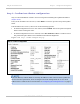
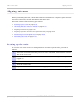
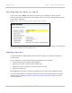

Table Of Contents
- PTP 250 User Guide
- Safety and regulatory information
- Contents
- List of Figures
- List of Tables
- About This User Guide
- Chapter 1: Product description
- Chapter 2: Planning considerations
- Chapter 3: Legal information
- Chapter 4: Reference information
- Chapter 5: Installation
- Chapter 6: Configuration and alignment
- Chapter 7: Operation
- Chapter 8: Troubleshooting
- Testing link end hardware
- Testing when PoE LEDs do not illuminate correctly
- Testing after a lightning strike
- Test flowcharts
- AC LED is off
- AC LED is flashing
- PORT LED is off
- PORT LED is flashing
- Test Ethernet packet errors reported by ODU
- Test Ethernet packet errors reported by managed switch or router
- Test ping packet loss
- Test resistance in the ODU cable
- Testing the radio link
- Testing link end hardware
- Glossary

PTP 250 User Guide Aligning antennas
phn-2182_003v004 (Oct 2011)
UNDER DEVELOPMENT
6-23
Aligning antennas
Before performing this task, check that hardware installation is complete (apart from the
network connections) at both the Master and Slave sites.
This task consists of the following procedures:
• Starting up the units on pa
ge 6-23
• Checking that the units are armed on page 6-24
• Aligning antennas on p
age 6-24
• Aligning separate antenna
s for spatial diversity on page 6-26
• Monitoring received signal level on
page 6-26.
• Disarming the units on
page 6-29
Starting up the units
To connect one of the units to a management PC and start up both units, proceed as
follows:
1
Select the unit from which this process is to be controlled; either Master or Slave.
This is the ‘local’ unit.
2
Check that the management PC is connected to the local unit, powered up and
logged on.
3
Start the local unit.
4
Start the remote unit.
5
Log into the local unit as described in Logging into the web interface on
page 6-6.