
User's Guide
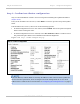
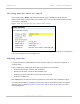
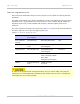


Table Of Contents
- PTP 250 User Guide
- Safety and regulatory information
- Contents
- List of Figures
- List of Tables
- About This User Guide
- Chapter 1: Product description
- Chapter 2: Planning considerations
- Chapter 3: Legal information
- Chapter 4: Reference information
- Chapter 5: Installation
- Chapter 6: Configuration and alignment
- Chapter 7: Operation
- Chapter 8: Troubleshooting
- Testing link end hardware
- Testing when PoE LEDs do not illuminate correctly
- Testing after a lightning strike
- Test flowcharts
- AC LED is off
- AC LED is flashing
- PORT LED is off
- PORT LED is flashing
- Test Ethernet packet errors reported by ODU
- Test Ethernet packet errors reported by managed switch or router
- Test ping packet loss
- Test resistance in the ODU cable
- Testing the radio link
- Testing link end hardware
- Glossary

Using the installation wizard Chapter 6: Configuration and alignment
6-22
UNDER DEVELOPMENT
phn-2182_003v004 (Oct 2011)
Step 5: Confirm installation configuration
Step 5 of the Installation wizard is for reviewing and confirming the updated attributes
(Figure 6-18).
I
f any of the attributes are incorrect, select Back to return to previous steps and update
them.
If all attributes are correct, choose one of the following options:
• If antenna alignment tones are not wanted, select Finish. This is the preferred option
before bench testing the units.
• If antenna alignment tones are wanted, select Set Armed and Yes to confirm. This is
the preferred option before site installation and antenna alignment.
Figure 6-18 Step 5: Confirm Configuration page
If the IP Address, Subnet Mask or Gateway IP Address of the unit have been updated to
meet network requirements, then reconfigure the local management PC to use an IP
address that is valid for the network. Refer to Configuring the management PC on page 6-
3.