
User's Guide

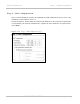
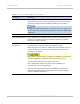
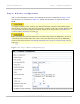

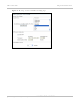
Table Of Contents
- PTP 250 User Guide
- Safety and regulatory information
- Contents
- List of Figures
- List of Tables
- About This User Guide
- Chapter 1: Product description
- Chapter 2: Planning considerations
- Chapter 3: Legal information
- Chapter 4: Reference information
- Chapter 5: Installation
- Chapter 6: Configuration and alignment
- Chapter 7: Operation
- Chapter 8: Troubleshooting
- Testing link end hardware
- Testing when PoE LEDs do not illuminate correctly
- Testing after a lightning strike
- Test flowcharts
- AC LED is off
- AC LED is flashing
- PORT LED is off
- PORT LED is flashing
- Test Ethernet packet errors reported by ODU
- Test Ethernet packet errors reported by managed switch or router
- Test ping packet loss
- Test resistance in the ODU cable
- Testing the radio link
- Testing link end hardware
- Glossary

Using the installation wizard Chapter 6: Configuration and alignment
6-18
UNDER DEVELOPMENT
phn-2182_003v004 (Oct 2011)
Attribute Meaning
Cable Loss Loss (dB) in the RF cable between the ODU and the antenna.
If there is a significant difference in length of the antenna cables
for the two antenna ports, then enter the average value.
Maximum Power
Level
The maximum power (dBm) at which the unit will transmit.
The highest value in the list is automatically constrained to be
within regulatory limts, based on the values entered in Antenna
Gain and Cable Loss.
Modulation Mode The modulation mode used on the transmit channel. The
recommended setting is ‘Adaptive’.
Encryption Key
(64 characters)
Key to be used for link encryption. The same key must be used at
both ends of the link.
Step 3: Date and time settings
Step 3 of the Installation wizard is for setting the date and time (Figure 6-16). The
attributes are described in Table 6-3. Update t
he attributes as required and select Next.
The clock supplies accurate date and time information to the system. It can be set to run
with or without a connection to a Network Time Protocol (NTP) server:
• In the absence of an NTP server connection, the clock can be set to run manually. The
clock is battery backed and will continue to operate for several days after the ODU is
switched off.
• If an NTP server connection is available, the clock can be set to synchronize with the
server time at regular intervals.