
User's Guide

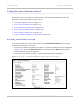
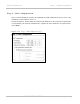
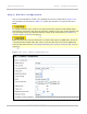
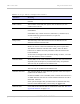

Table Of Contents
- PTP 250 User Guide
- Safety and regulatory information
- Contents
- List of Figures
- List of Tables
- About This User Guide
- Chapter 1: Product description
- Chapter 2: Planning considerations
- Chapter 3: Legal information
- Chapter 4: Reference information
- Chapter 5: Installation
- Chapter 6: Configuration and alignment
- Chapter 7: Operation
- Chapter 8: Troubleshooting
- Testing link end hardware
- Testing when PoE LEDs do not illuminate correctly
- Testing after a lightning strike
- Test flowcharts
- AC LED is off
- AC LED is flashing
- PORT LED is off
- PORT LED is flashing
- Test Ethernet packet errors reported by ODU
- Test Ethernet packet errors reported by managed switch or router
- Test ping packet loss
- Test resistance in the ODU cable
- Testing the radio link
- Testing link end hardware
- Glossary

PTP 250 User Guide Using the installation wizard
phn-2182_003v004 (Oct 2011)
UNDER DEVELOPMENT
6-17
Table 6-2 Step 2: Wireless Configuration attributes
Attribute Meaning
System Name A name for the link. Spaces are not allowed, so use underscores
instead.
End Location The location of the link end. Spaces are not allowed, so use
underscores instead.
Link Name (ESSID) A link can only be established between units that have identical
Link Names.
Link Name may consist of letters (A-Z and a-z), numbers (0-9)
and the following special characters (no spaces):
(),-.,:<=>[]_{}
Range (km) The link range. The value must not be less than the actual
distance between the link ends.
Master/Slave Mode Each link consists of one ‘Master’ and one ‘Slave’ unit. The
Master is used to control and maintain the point-to-point link.
The Master transmits until the link is made, while the Slave
listens for its Master and only transmits when the Master has
been identified.
As all units are shipped with a default setting of ‘Slave’, one unit
in the link must be reset to ‘Master’.
Channel Width Width (MHz) of the radio channel used by this link. The selection
depends upon the frequency variant and country of operation.
This can only be updated at the Master unit.
Band The frequency band (GHz) in which this link operates.
This can only be updated at the Master unit.
Channel Selection The channel (MHz) in which this link operates. This can only be
updated at the Master unit.
If Channel Width is set to 40 MHz, then each tick box selects two
20 MHz channels: the first is Current Channel and the second is
Extended Channel.
If the system designer has provided a list of channels that may
interfere with TDWR radars, ensure they are unselected.
Antenna Gain Gain (dBi) of the antenna that is connected to this unit. See FCC
approved antennas on page 2-30.