
User's Guide

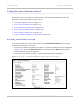
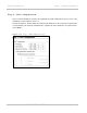
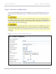

Table Of Contents
- PTP 250 User Guide
- Safety and regulatory information
- Contents
- List of Figures
- List of Tables
- About This User Guide
- Chapter 1: Product description
- Chapter 2: Planning considerations
- Chapter 3: Legal information
- Chapter 4: Reference information
- Chapter 5: Installation
- Chapter 6: Configuration and alignment
- Chapter 7: Operation
- Chapter 8: Troubleshooting
- Testing link end hardware
- Testing when PoE LEDs do not illuminate correctly
- Testing after a lightning strike
- Test flowcharts
- AC LED is off
- AC LED is flashing
- PORT LED is off
- PORT LED is flashing
- Test Ethernet packet errors reported by ODU
- Test Ethernet packet errors reported by managed switch or router
- Test ping packet loss
- Test resistance in the ODU cable
- Testing the radio link
- Testing link end hardware
- Glossary

Using the installation wizard Chapter 6: Configuration and alignment
6-16
UNDER DEVELOPMENT
phn-2182_003v004 (Oct 2011)
Step 2: Wireless configuration
Step 2 of the Installation wizard is for updating the wireless configuration (Figure 6-15).
The attributes are described in Table 6-2. Up
date the attributes as required and select
Next.
To comply with FCC rules, unselect any channels that may interfere with TDWR radars.
This must be done before the units are allowed to radiate on site. The system designer will
have provided a list of any affected channels, based on the instructions in Avoidance of
weather radars (USA only) on page 2-5.
When operating with external antennas in countries that impose an EIRP limit, choose an
external antenna and RF cable that will not cause the PTP 250 to exceed the EIRP limit,
based on the instructions in Calculating maximum power level for connectorized units on
page 2-13.
Figure 6-15 Step 2: Wireless Configuration page