
User's Guide
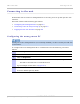
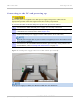


Table Of Contents
- PTP 250 User Guide
- Safety and regulatory information
- Contents
- List of Figures
- List of Tables
- About This User Guide
- Chapter 1: Product description
- Chapter 2: Planning considerations
- Chapter 3: Legal information
- Chapter 4: Reference information
- Chapter 5: Installation
- Chapter 6: Configuration and alignment
- Chapter 7: Operation
- Chapter 8: Troubleshooting
- Testing link end hardware
- Testing when PoE LEDs do not illuminate correctly
- Testing after a lightning strike
- Test flowcharts
- AC LED is off
- AC LED is flashing
- PORT LED is off
- PORT LED is flashing
- Test Ethernet packet errors reported by ODU
- Test Ethernet packet errors reported by managed switch or router
- Test ping packet loss
- Test resistance in the ODU cable
- Testing the radio link
- Testing link end hardware
- Glossary

PTP 250 User Guide Connecting to the unit
phn-2182_003v004 (Oct 2011)
UNDER DEVELOPMENT
6-5
Connecting to the PC and powering up
Ensure AC power is supplied to the PoE power supply using an AC cable with an
appropriate ground connection approved for the country of operation.
To connect the ODU to the PC and power up the unit, proceed as follows:
1
Check that the ODU and PoE power supply are correctly connected.
2
Connect the PC Ethernet port to the DATA IN port of the PoE power supply using
a standard (not crossed) Cat5e cable (Figure 6-3).
3
Connect the PoE power supply to an AC outlet (100 V AC to 240 V AC).
The PoE power supply has no power switch. It supplies power to the ODU as soon
as AC power is applied.
4
Check that the AC and PORT LEDs illuminate (green steady). If they blink or do
not illuminate, refer to Testing link end hardware on
page 8-2.
Figure 6-3 PoE power supply connected to ODU and PC (or network)
If the power supply is a PIDU, the Ethernet LED does not illuminate.