
User's Guide
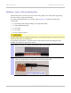
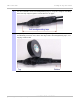
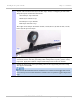
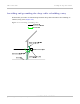
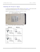
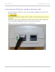
Table Of Contents
- PTP 250 User Guide
- Safety and regulatory information
- Contents
- List of Figures
- List of Tables
- About This User Guide
- Chapter 1: Product description
- Chapter 2: Planning considerations
- Chapter 3: Legal information
- Chapter 4: Reference information
- Chapter 5: Installation
- Chapter 6: Configuration and alignment
- Chapter 7: Operation
- Chapter 8: Troubleshooting
- Testing link end hardware
- Testing when PoE LEDs do not illuminate correctly
- Testing after a lightning strike
- Test flowcharts
- AC LED is off
- AC LED is flashing
- PORT LED is off
- PORT LED is flashing
- Test Ethernet packet errors reported by ODU
- Test Ethernet packet errors reported by managed switch or router
- Test ping packet loss
- Test resistance in the ODU cable
- Testing the radio link
- Testing link end hardware
- Glossary

Installing the PoE power supply Chapter 5: Installation
5-32
UNDER DEVELOPMENT
phn-2182_003v004 (Oct 2011)
Preparing the PoE power supply to network equipment cable
Prepare the CAT5e cable that will connect the PoE power supply to the network
equipment. This cable must meet the following requirements:
• Use either foil screen (FTP) or braided screen (STP) cable.
•
Use screened RJ45 connectors with metal shells at both ends.
•
Ensure there is a continuous electrical connection between both screened connectors.
The connected network equipment must feature screened RJ45 connectors and must be
connected to ground, otherwise the PoE power supply will not be grounded.
The PoE power supply is not normally connected to the network equipment until antenna
alignment is complete. See Connecting to the network on
page 6-34.