
User's Guide
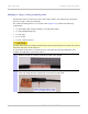
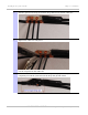
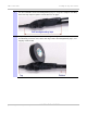
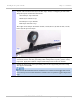
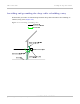
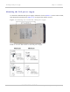
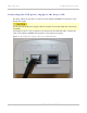
Table Of Contents
- PTP 250 User Guide
- Safety and regulatory information
- Contents
- List of Figures
- List of Tables
- About This User Guide
- Chapter 1: Product description
- Chapter 2: Planning considerations
- Chapter 3: Legal information
- Chapter 4: Reference information
- Chapter 5: Installation
- Chapter 6: Configuration and alignment
- Chapter 7: Operation
- Chapter 8: Troubleshooting
- Testing link end hardware
- Testing when PoE LEDs do not illuminate correctly
- Testing after a lightning strike
- Test flowcharts
- AC LED is off
- AC LED is flashing
- PORT LED is off
- PORT LED is flashing
- Test Ethernet packet errors reported by ODU
- Test Ethernet packet errors reported by managed switch or router
- Test ping packet loss
- Test resistance in the ODU cable
- Testing the radio link
- Testing link end hardware
- Glossary

PTP 250 User Guide Installing the PoE power supply
phn-2182_003v004 (Oct 2011)
UNDER DEVELOPMENT
5-31
Connecting the PoE power supply to the drop cable
The drop cable from the ODU is connected to the DATA & POWER OUT interface of the
PoE power supply.
Do not dress the PoE power supply cables too tightly, as this may make the connections
unreliable.
Fit an RJ45 connector (but no gland) to the PoE end of the LPU-PoE cable. Connect the
cable to the DATA & POWER OUT interface of the PoE power supply.
Figure 5-10 PoE power supply connected to LPU-PoE cable