
User's Guide
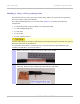
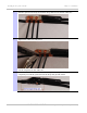
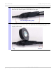
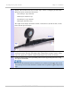
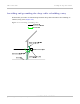
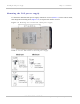
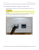
Table Of Contents
- PTP 250 User Guide
- Safety and regulatory information
- Contents
- List of Figures
- List of Tables
- About This User Guide
- Chapter 1: Product description
- Chapter 2: Planning considerations
- Chapter 3: Legal information
- Chapter 4: Reference information
- Chapter 5: Installation
- Chapter 6: Configuration and alignment
- Chapter 7: Operation
- Chapter 8: Troubleshooting
- Testing link end hardware
- Testing when PoE LEDs do not illuminate correctly
- Testing after a lightning strike
- Test flowcharts
- AC LED is off
- AC LED is flashing
- PORT LED is off
- PORT LED is flashing
- Test Ethernet packet errors reported by ODU
- Test Ethernet packet errors reported by managed switch or router
- Test ping packet loss
- Test resistance in the ODU cable
- Testing the radio link
- Testing link end hardware
- Glossary

Installing the drop cable and LPU Chapter 5: Installation
5-26
UNDER DEVELOPMENT
phn-2182_003v004 (Oct 2011)
8
Repeat with a further four layers of PVC tape, always overlapping at half width.
Wrap the layers in alternate directions:
Second layer: top to bottom.
Third layer: bottom to top.
Fourth layer: top to bottom.
Fifth layer: bottom to top.
The edges of each layer should be 25mm (1 inch) above (A) and 25 mm (1 inch)
below (B) the previous layer.
9
Prepare the metal grounding point of the supporting structure to provide a good
electrical contact with the grounding cable clamp. Remove paint, grease or dirt,
if present. Apply anti-oxidant compound liberally between the two metals.
10
Clamp the bottom lug of the grounding cable to the supporting structure using
site approved methods.
The manual
R56 Standards And Guidelines For Communication Sites
states that
two-hole lugs secured with fasteners in both holes are preferred over single-hole
lugs.