
User's Guide
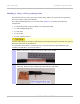
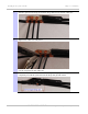
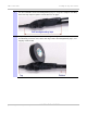
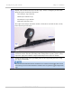
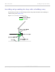
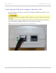
Table Of Contents
- PTP 250 User Guide
- Safety and regulatory information
- Contents
- List of Figures
- List of Tables
- About This User Guide
- Chapter 1: Product description
- Chapter 2: Planning considerations
- Chapter 3: Legal information
- Chapter 4: Reference information
- Chapter 5: Installation
- Chapter 6: Configuration and alignment
- Chapter 7: Operation
- Chapter 8: Troubleshooting
- Testing link end hardware
- Testing when PoE LEDs do not illuminate correctly
- Testing after a lightning strike
- Test flowcharts
- AC LED is off
- AC LED is flashing
- PORT LED is off
- PORT LED is flashing
- Test Ethernet packet errors reported by ODU
- Test Ethernet packet errors reported by managed switch or router
- Test ping packet loss
- Test resistance in the ODU cable
- Testing the radio link
- Testing link end hardware
- Glossary

PTP 250 User Guide Installing the drop cable and LPU
phn-2182_003v004 (Oct 2011)
UNDER DEVELOPMENT
5-25
6
Use the remainder of the self-amalgamating tape to wrap the complete assembly.
Press the tape edges together so that there are no gaps.
7
Wrap a layer of PVC tape from bottom to top, starting from 25 mm (1 inch) below
and finishing 25 mm (1 inch) above the edge of the self-amalgamating tape, over
lapping at half width.