
User's Guide
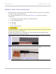
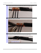
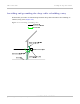
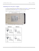
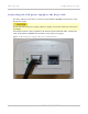
Table Of Contents
- PTP 250 User Guide
- Safety and regulatory information
- Contents
- List of Figures
- List of Tables
- About This User Guide
- Chapter 1: Product description
- Chapter 2: Planning considerations
- Chapter 3: Legal information
- Chapter 4: Reference information
- Chapter 5: Installation
- Chapter 6: Configuration and alignment
- Chapter 7: Operation
- Chapter 8: Troubleshooting
- Testing link end hardware
- Testing when PoE LEDs do not illuminate correctly
- Testing after a lightning strike
- Test flowcharts
- AC LED is off
- AC LED is flashing
- PORT LED is off
- PORT LED is flashing
- Test Ethernet packet errors reported by ODU
- Test Ethernet packet errors reported by managed switch or router
- Test ping packet loss
- Test resistance in the ODU cable
- Testing the radio link
- Testing link end hardware
- Glossary

PTP 250 User Guide Installing the drop cable and LPU
phn-2182_003v004 (Oct 2011)
UNDER DEVELOPMENT
5-23
Making a drop cable ground point
Perform this task to connect the screen of the drop cable to the metal of the supporting
structure using a cable grounding kit.
The cable grounding kit for 1/4” and 3/8” cable (Figure 1-8) co
ntains the following
components:
• 1 x grounding cable with grounding 2 hole lug fitted (M10)
• 1 x self Amalgamating tape
• 1 x PVC tape
• 3 x tie wraps
• 2 x bolt, washer and nut
Ground cables must be installed without drip loops and pointing down towards the ground;
otherwise they may not be effective.
To ground the drop cable to a metal structure using the Motorola grounding kit (part
number 01010419001), proceed as follows:
1
Remove 60 mm (2.5 inches) of the drop cable outer sheath.
2
Cut 38mm (1.5 inches) of rubber tape (self amalgamating) and fit to the ground
cable lug. Wrap the tape completely around the lug and cable.