
User's Guide

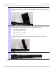

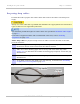
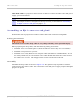
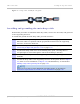
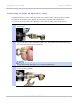
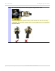
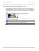
Table Of Contents
- PTP 250 User Guide
- Safety and regulatory information
- Contents
- List of Figures
- List of Tables
- About This User Guide
- Chapter 1: Product description
- Chapter 2: Planning considerations
- Chapter 3: Legal information
- Chapter 4: Reference information
- Chapter 5: Installation
- Chapter 6: Configuration and alignment
- Chapter 7: Operation
- Chapter 8: Troubleshooting
- Testing link end hardware
- Testing when PoE LEDs do not illuminate correctly
- Testing after a lightning strike
- Test flowcharts
- AC LED is off
- AC LED is flashing
- PORT LED is off
- PORT LED is flashing
- Test Ethernet packet errors reported by ODU
- Test Ethernet packet errors reported by managed switch or router
- Test ping packet loss
- Test resistance in the ODU cable
- Testing the radio link
- Testing link end hardware
- Glossary

Installing the drop cable and LPU Chapter 5: Installation
5-20
UNDER DEVELOPMENT
phn-2182_003v004 (Oct 2011)
Connecting an RJ45 and gland to a unit
Perform this task to connect the drop cable to an ODU or LPU. This procedure contains
illustrations of an ODU, but it applies in principle to both the ODU and the LPU.
To connect the drop cable with a gland to a unit (LPU or ODU), proceed as follows:
1
Insert the RJ45 plug into the socket in the unit, making sure that the locking tab
snaps home.
2
Support the drop cable and gently hand screw the gland body into the unit until
the O ring seal is flush to the unit body.
Do not fit the back shell prior to securing the gland body.
3
Once the gland is fully hand screwed into the unit, tighten it with a spanner to
torque 10 Nm (7.4 ftlbs).