
User's Guide

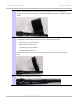

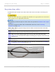

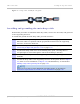
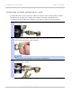
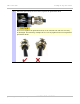

Table Of Contents
- PTP 250 User Guide
- Safety and regulatory information
- Contents
- List of Figures
- List of Tables
- About This User Guide
- Chapter 1: Product description
- Chapter 2: Planning considerations
- Chapter 3: Legal information
- Chapter 4: Reference information
- Chapter 5: Installation
- Chapter 6: Configuration and alignment
- Chapter 7: Operation
- Chapter 8: Troubleshooting
- Testing link end hardware
- Testing when PoE LEDs do not illuminate correctly
- Testing after a lightning strike
- Test flowcharts
- AC LED is off
- AC LED is flashing
- PORT LED is off
- PORT LED is flashing
- Test Ethernet packet errors reported by ODU
- Test Ethernet packet errors reported by managed switch or router
- Test ping packet loss
- Test resistance in the ODU cable
- Testing the radio link
- Testing link end hardware
- Glossary

Installing the drop cable and LPU Chapter 5: Installation
5-18
UNDER DEVELOPMENT
phn-2182_003v004 (Oct 2011)
Figure 5-6 Correct cable preparation for drop cable of the supported type
Check that the crimp tool matches the RJ45 connector being used; otherwise the cable or
connector may be damaged.
The cable inner sheath must be located correctly under the connector housing tang. If this
is not done correctly, there is no strain relief on the cable terminations.
Figure 5-7 s
hows the end of a drop cable fitted with an RJ45 plug and a gland.