
User's Guide

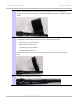

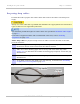
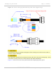
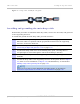
Table Of Contents
- PTP 250 User Guide
- Safety and regulatory information
- Contents
- List of Figures
- List of Tables
- About This User Guide
- Chapter 1: Product description
- Chapter 2: Planning considerations
- Chapter 3: Legal information
- Chapter 4: Reference information
- Chapter 5: Installation
- Chapter 6: Configuration and alignment
- Chapter 7: Operation
- Chapter 8: Troubleshooting
- Testing link end hardware
- Testing when PoE LEDs do not illuminate correctly
- Testing after a lightning strike
- Test flowcharts
- AC LED is off
- AC LED is flashing
- PORT LED is off
- PORT LED is flashing
- Test Ethernet packet errors reported by ODU
- Test Ethernet packet errors reported by managed switch or router
- Test ping packet loss
- Test resistance in the ODU cable
- Testing the radio link
- Testing link end hardware
- Glossary

Installing the drop cable and LPU Chapter 5: Installation
5-16
UNDER DEVELOPMENT
phn-2182_003v004 (Oct 2011)
Preparing drop cables
Perform this task to prepare the CAT5e cables that connect the ODU to the PoE power
supply.
Always use Cat5e cable that is gel-filled and shielded with copper-plated steel. Alternative
types of cable are not supported by Motorola.
The maximum permitted lengths of CAT5e cables are specified in Maximum cable lengths
on page 2-7.
For details of supported cables and recommended connectors, refer to Ordering
components on page 2-24.
‘Main’ drop cable: To prepare a long section of cable to connect the ODU to the LPU,
proceed as follows:
1
Cut off the approximate length required (allowing a bit of surplus), or leave it on
the drum so that it can be unwound as the cable is hoisted.
2
Slide one or more hoisting grips onto to the top end of the main drop cable
(Figure 5-5). To det
ermine the number of hoisting grips required, consult the grip
manufacturer.
3
Secure the hoisting grip to the cable using a special tool, as recommended by the
manufacturer.
4
Fit an RJ45 connector and gland to the top end only, as described in Assembling
an RJ45 conne
ctor and gland on page 5-17.
Figure 5-5 Typical hoisting grip on cable