
User's Guide
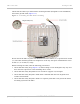
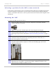
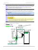
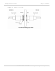
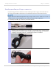
Table Of Contents
- PTP 250 User Guide
- Safety and regulatory information
- Contents
- List of Figures
- List of Tables
- About This User Guide
- Chapter 1: Product description
- Chapter 2: Planning considerations
- Chapter 3: Legal information
- Chapter 4: Reference information
- Chapter 5: Installation
- Chapter 6: Configuration and alignment
- Chapter 7: Operation
- Chapter 8: Troubleshooting
- Testing link end hardware
- Testing when PoE LEDs do not illuminate correctly
- Testing after a lightning strike
- Test flowcharts
- AC LED is off
- AC LED is flashing
- PORT LED is off
- PORT LED is flashing
- Test Ethernet packet errors reported by ODU
- Test Ethernet packet errors reported by managed switch or router
- Test ping packet loss
- Test resistance in the ODU cable
- Testing the radio link
- Testing link end hardware
- Glossary

PTP 250 User Guide Installing connectorized antennas
phn-2182_003v004 (Oct 2011)
UNDER DEVELOPMENT
5-9
5
If the ODU is mounted outdoors, weatherproof the N type connectors fitted to the
ODU by following the procedure Weatherproofing an N type connector on page 5-
12. We
atherproof the antenna joints in the same way (unless the antenna
manufacturer specifies a different method).
6
Ground the antenna cables to the supporting structure at the correct points
(Figure 5-4). They should be grounded wit
hin 0.3 meters (1 foot) of the ODU and
antennas using the using the cable grounding kit (part number 01010419001).
A mast or tower may require additional grounding points, as specified in
Protection requirements for a mast or tower installation on page 2-18.
7
Dress the antenna cables and attach them to the supporting structure using site
approved methods.
Ensure that no undue strain is placed on the ODU or antenna connectors. Ensure
that the cables do not flap in the wind, as flapping cables are prone to damage
and induce unwanted vibrations in the supporting structure.
Figure 5-2 Lightning arrestor mounting