
User's Guide
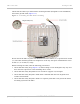
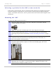
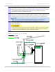
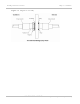
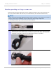
Table Of Contents
- PTP 250 User Guide
- Safety and regulatory information
- Contents
- List of Figures
- List of Tables
- About This User Guide
- Chapter 1: Product description
- Chapter 2: Planning considerations
- Chapter 3: Legal information
- Chapter 4: Reference information
- Chapter 5: Installation
- Chapter 6: Configuration and alignment
- Chapter 7: Operation
- Chapter 8: Troubleshooting
- Testing link end hardware
- Testing when PoE LEDs do not illuminate correctly
- Testing after a lightning strike
- Test flowcharts
- AC LED is off
- AC LED is flashing
- PORT LED is off
- PORT LED is flashing
- Test Ethernet packet errors reported by ODU
- Test Ethernet packet errors reported by managed switch or router
- Test ping packet loss
- Test resistance in the ODU cable
- Testing the radio link
- Testing link end hardware
- Glossary

Installing connectorized antennas Chapter 5: Installation
5-8
UNDER DEVELOPMENT
phn-2182_003v004 (Oct 2011)
Installing connectorized antennas
If the ODU is connectorized, perform this task to install separate antenna(s).
Preparing for connectorized installations
Before proceeding with the installation, perform the following checks:
• Check that the correct components are available, as described in Ordering components
on page 2-24.
• Check
that the selected antenna conforms to the applicable regulatory restrictions, as
described in FCC approved antennas on
page 2-30 and Compliance with radio
regulations on page 4-12.
• Check
that the correct tools are available. The tools required for mounting the
antennas are specific to the antenna chosen. Refer to the antenna manufacturer’s
instructions.
Mounting and connecting antennas
To mount and connect the antenna(s), proceed as follows:
1
Mount the antenna(s) according to manufacturer’s instructions. When using
separate antennas to achieve spatial diversity, mount one with Horizontal
polarization and the other with Vertical polarization.
2
Connect the ODU to the antenna with cables of type LMR100, LMR200, LMR300,
LMR400 or LMR600. Connect the ODU ‘V’ interface to the vertical polarization
antenna and connect the ODU ‘H interface to the horizontal polarization antenna
(Figure 1-5).
When using separate antennas to achieve spatial diversity, the antenna cables
will be disconnected from the ODU during the alignment procedure. Therefore,
do not weatherproof the ODU joints until antenna alignment is complete.
3
Where the ODU is mounted indoors, install lightning arrestors at the building
entry point (Figure 5-2). Assemble
the Polyphaser LSXL-ME or LSXL as shown in
Figure 5-3. Conne
ct the lighting arrestors to the master ground bar of the
building.
4
When dressing the antenna cables, form drip loops near the lower ends. These
ensure that water is not constantly channeled towards the connectors.