
User's Guide
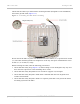
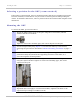

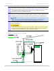
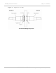
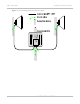
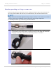
Table Of Contents
- PTP 250 User Guide
- Safety and regulatory information
- Contents
- List of Figures
- List of Tables
- About This User Guide
- Chapter 1: Product description
- Chapter 2: Planning considerations
- Chapter 3: Legal information
- Chapter 4: Reference information
- Chapter 5: Installation
- Chapter 6: Configuration and alignment
- Chapter 7: Operation
- Chapter 8: Troubleshooting
- Testing link end hardware
- Testing when PoE LEDs do not illuminate correctly
- Testing after a lightning strike
- Test flowcharts
- AC LED is off
- AC LED is flashing
- PORT LED is off
- PORT LED is flashing
- Test Ethernet packet errors reported by ODU
- Test Ethernet packet errors reported by managed switch or router
- Test ping packet loss
- Test resistance in the ODU cable
- Testing the radio link
- Testing link end hardware
- Glossary

Installing the ODU Chapter 5: Installation
5-6
UNDER DEVELOPMENT
phn-2182_003v004 (Oct 2011)
Selecting a position for the ODU (connectorized)
If the ODU is connectorized, select a mounting position that gives it maximum protection
from the elements, but still allows easy access for connecting and weatherproofing the
cables. To minimize cable losses, select a position where the antenna cable lengths can be
minimized.
Mounting the ODU
To mount the ODU, proceed as follows:
1
Attach the ODU bracket strap to the pole using M8 x 70 mm bolts, M8 flat
washers and M8 coil washers.
Tighten to ensure the assembly grips, but can be adjusted on the pole.
2
Use the integral safety loop (Figure 5-1) to hoi
st the ODU up to the bracket,
observing the precautions described in Checks and safety precautions on
page 5-
4.
3
When the ODU is in position, use the safety loop as a fixing point to secure a
permanent safety lanyard from the supporting structure to the ODU, as a
precaution against mounting failure.
4
Offer the ODU (with pre-fitted mounting bracket) to the bracket strap and affix
using the captive M8 bolt. Tighten to ensure the assembly grips, but can be
adjusted on the pole.
5
Adjust the elevation and azimuth of the unit to achieve an approximate visual
alignment (does not apply to connectorized ODUs). Tighten both bolts to the
required torque settings of 14 Nm (11 lb ft).