
User's Guide
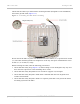
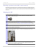

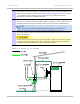
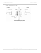
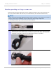
Table Of Contents
- PTP 250 User Guide
- Safety and regulatory information
- Contents
- List of Figures
- List of Tables
- About This User Guide
- Chapter 1: Product description
- Chapter 2: Planning considerations
- Chapter 3: Legal information
- Chapter 4: Reference information
- Chapter 5: Installation
- Chapter 6: Configuration and alignment
- Chapter 7: Operation
- Chapter 8: Troubleshooting
- Testing link end hardware
- Testing when PoE LEDs do not illuminate correctly
- Testing after a lightning strike
- Test flowcharts
- AC LED is off
- AC LED is flashing
- PORT LED is off
- PORT LED is flashing
- Test Ethernet packet errors reported by ODU
- Test Ethernet packet errors reported by managed switch or router
- Test ping packet loss
- Test resistance in the ODU cable
- Testing the radio link
- Testing link end hardware
- Glossary

PTP 250 User Guide Installing the ODU
phn-2182_003v004 (Oct 2011)
UNDER DEVELOPMENT
5-5
Check that the ODU is pre-fitted with a mounting bracket (designed to ease installation)
and with a ground cable (Figure 5-1).
Figu
re 5-1 Checking the ODU before mounting
Do not mount the ODU on poles with diameter less than 50mm (2”) or greater than 75mm
(3”). The ODU mounting bracket is designed to work only with poles with diameter in the
50 mm (2”) to 75 mm (3”) range.
Before hoisting the ODU, take the following precautions:
• Check that the safety loop (Figure 5-1) and its
fixing are not damaged in any way and
have not been exposed to a shock loading due to a fall.
• Check that the safety lanyard does not exceed 1m (approx 3 ft) in length.
• Check that the safety lanyard is made from a material that does not degrade in an
outdoor environment.
• Check that the safety lanyard is fixed to a separate point that is not part of the direct
mounting system for the ODU.