
User's Guide
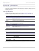

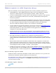
Table Of Contents
- PTP 250 User Guide
- Safety and regulatory information
- Contents
- List of Figures
- List of Tables
- About This User Guide
- Chapter 1: Product description
- Chapter 2: Planning considerations
- Chapter 3: Legal information
- Chapter 4: Reference information
- Chapter 5: Installation
- Chapter 6: Configuration and alignment
- Chapter 7: Operation
- Chapter 8: Troubleshooting
- Testing link end hardware
- Testing when PoE LEDs do not illuminate correctly
- Testing after a lightning strike
- Test flowcharts
- AC LED is off
- AC LED is flashing
- PORT LED is off
- PORT LED is flashing
- Test Ethernet packet errors reported by ODU
- Test Ethernet packet errors reported by managed switch or router
- Test ping packet loss
- Test resistance in the ODU cable
- Testing the radio link
- Testing link end hardware
- Glossary

Compliance with safety standards Chapter 4: Reference information
4-10
UNDER DEVELOPMENT
phn-2182_003v004 (Oct 2011)
The following calculation is based on the ANSI IEEE C95.1-1991 method, as that provides
a worst case analysis. Details of the assessment to EN50383:2002 can be provided, if
required.
Peak power density in the far field of a radio frequency point source is calculated as
follows:
Where: Is:
S
power density in W/m
2
P
maximum average transmit power
capability of the radio, in W
G
total Tx gain as a factor, converted
from dB
d
distance from point source, in m.
Rearranging terms to solve for distance yields:
Calculated distances and power compliance margins
Table 4-13 shows calculated minimum separation distances, recommended distances and
resulting margins for each frequency band and antenna combination. These are
conservative distances that include compliance margins. At these and greater separation
distances, the power density from the RF field is below generally accepted limits for the
general population.
Explanation of terms used in Table 4-13:
Tx burst –
maximum average transmit power in burst (Watt)
P – maximum average transmit power capability of the radio (Watt)
G – total transmit gain as a factor, converted from dB
S – power density (W/m
2
)
d – minimum distance from point source (meters)
R – recommended distances (meters)
2
4
.
d
GP
S
π
=
S
GP
d
.4
.
π
=