
User's Manual


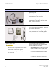


Table Of Contents
- PTP 250 User Guide
- Copyrights
- Safety and regulatory information
- Contents
- List of Figures
- List of Tables
- About This User Guide
- Chapter 1 Product description
- Chapter 2 Planning considerations
- Chapter 3 Legal information
- Chapter 4 Reference information
- Chapter 5 Installation
- Chapter 6 Configuration and alignment
- Chapter 7 Operation
- Chapter 8 Troubleshooting
- Testing link end hardware
- Testing when PoE LEDs do not illuminate correctly
- Testing after a lightning strike
- Test flowcharts
- AC LED is off
- AC LED is flashing
- PORT LED is off
- PORT LED is flashing
- Test Ethernet packet errors reported by ODU
- Test Ethernet packet errors reported by managed switch or router
- Test ping packet loss
- Test resistance at the PoE end of the drop cable
- Testing the radio link
- Testing link end hardware
- Glossary

Installation inventories Chapter 4 Reference information
phn-2182_002v000
4-8
May 2011
Item Notes
N type male connectors
For connecting the RF cables to the ODU.
Two connectors required per ODU. Use
weatherproof connectors, preferably ones
that are supplied with adhesive lined heat
shrink sleeves that are fitted over the
cable/connector interface.
‘RF CONNECTOR,N,MALE,STRAIGHT FOR
CNT-400 CABLE’. Motorola part number
09010091001.
NOTE
For the antenna end of the RF cable,
refer to the antenna manufacturer’s
instructions.
Self-amalgamating and PVC tape To weatherproof the RF connectors.
Cable grounding kits One kit is required per antenna cable
grounding point.
Refer to Table 4-3 for
specifications and part
numbers.
Cable ties, cable cleats For securing antenna cables.
Lightning arrestor For protecting the antenna cable at building
entry, when the ODU is mounted indoors.
One required per antenna cable.
For example: Polyphaser LSXL-ME or LSXL.