
User's Manual


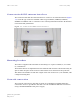

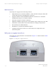
Table Of Contents
- PTP 250 User Guide
- Copyrights
- Safety and regulatory information
- Contents
- List of Figures
- List of Tables
- About This User Guide
- Chapter 1 Product description
- Chapter 2 Planning considerations
- Chapter 3 Legal information
- Chapter 4 Reference information
- Chapter 5 Installation
- Chapter 6 Configuration and alignment
- Chapter 7 Operation
- Chapter 8 Troubleshooting
- Testing link end hardware
- Testing when PoE LEDs do not illuminate correctly
- Testing after a lightning strike
- Test flowcharts
- AC LED is off
- AC LED is flashing
- PORT LED is off
- PORT LED is flashing
- Test Ethernet packet errors reported by ODU
- Test Ethernet packet errors reported by managed switch or router
- Test ping packet loss
- Test resistance at the PoE end of the drop cable
- Testing the radio link
- Testing link end hardware
- Glossary

PTP 250 User Guide Overview of the PTP 250
phn-2182_002v000
May 2011
1-3
802.11n device
PTP250 uses 802.11n encoding and radio transmission. In areas where the PTP 250
co-exists with 802.11a and 802.11n devices, the PTP 250 detects the 802.11a and
802.11n radio signals and chooses a clear channel away from any interference.
Avoiding interference from nearby devices
At initialization, the products monitor the available frequency channels to find a
channel that is clear of interference.
Typical deployment
The PTP 250 bridge consists of a pair of identical units, one deployed at each end of
the link. The radio link operates on a single frequency channel. One unit is configured
as a master and the other as a slave. The master unit takes responsibility for
controlling the link in both directions.
The bridge is aimed at a wide range of applications. One example is an enterprise that
needs to connect together the Local Area Network (LAN) of two or more buildings as
shown in Figure 1-1.
Figu
re 1-1 Typical PTP 250 bridge deployment (grounding not shown)