
User's Manual

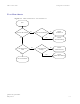


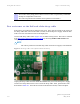
Table Of Contents
- PTP 250 User Guide
- Copyrights
- Safety and regulatory information
- Contents
- List of Figures
- List of Tables
- About This User Guide
- Chapter 1 Product description
- Chapter 2 Planning considerations
- Chapter 3 Legal information
- Chapter 4 Reference information
- Chapter 5 Installation
- Chapter 6 Configuration and alignment
- Chapter 7 Operation
- Chapter 8 Troubleshooting
- Testing link end hardware
- Testing when PoE LEDs do not illuminate correctly
- Testing after a lightning strike
- Test flowcharts
- AC LED is off
- AC LED is flashing
- PORT LED is off
- PORT LED is flashing
- Test Ethernet packet errors reported by ODU
- Test Ethernet packet errors reported by managed switch or router
- Test ping packet loss
- Test resistance at the PoE end of the drop cable
- Testing the radio link
- Testing link end hardware
- Glossary

Chapter 8
phn-2182_002v000
May 2011
8-1
Chapter 8 Troubleshooting
. . . . . . . . . . . . . . . . . . . . . . . . . . . . . . . . . . . . . . . . . . . . . . . . . . . . . . . . . . . .
.
.
.
.
This chapter contains procedures for identifying and correcting faults in a PTP 250
link. These procedures can be performed either on a newly installed link, or on an
operational link if communication is lost, or after a lightning strike.
The following topics are described in this chapter:
• Testing link end hardware on
page 8-2 describes how to test the link end
hardware, either when it fails on startup, or after a lightning strike.
• Testing the radio link on
page 8-12 describes how to test the link when there is
no radio communication, or when it is unreliable, or when the data throughput
rate is too low