
User's Manual
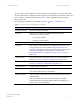
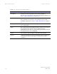
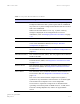
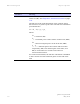

Table Of Contents
- PTP 250 User Guide
- Copyrights
- Safety and regulatory information
- Contents
- List of Figures
- List of Tables
- About This User Guide
- Chapter 1 Product description
- Chapter 2 Planning considerations
- Chapter 3 Legal information
- Chapter 4 Reference information
- Chapter 5 Installation
- Chapter 6 Configuration and alignment
- Chapter 7 Operation
- Chapter 8 Troubleshooting
- Testing link end hardware
- Testing when PoE LEDs do not illuminate correctly
- Testing after a lightning strike
- Test flowcharts
- AC LED is off
- AC LED is flashing
- PORT LED is off
- PORT LED is flashing
- Test Ethernet packet errors reported by ODU
- Test Ethernet packet errors reported by managed switch or router
- Test ping packet loss
- Test resistance at the PoE end of the drop cable
- Testing the radio link
- Testing link end hardware
- Glossary

PTP 250 User Guide Web-based management
phn-2182_002v000
May 2011
7-13
Attribute Meaning
V/H Ratio The maximum, mean, minimum and latest measurements of
V/H Ratio. See Diagnostics calculated over time on
page 7-23.
This is calculated from:
Power received by the vertical antenna input (dB) ÷
Power received by the horizontal antenna input (dB)
V/H Ratio is an aid to debugging a link. If it has a large
positive or negative value, then investigate the following
potential problems:
An antenna coaxial lead may be disconnected.
When spatial diversity is employed, the antenna with the
lower value may be pointing in the wrong direction.
When a dual polar antenna is deployed, the antenna may
be directed using a side lobe rather than the main lobe.
When there is a reflection from water on the link and spatial
diversity is employed, then one expects large, slow swings in
V/H Ratio. This indicates the antenna system is doing exactly
as intended.
Transmit Data
Rate
The maximum, mean, minimum and latest measurements of
Transmit Data Rate (Mbps). See Diagnostics calculated over
time on
page 7-23.
Receive Data Rate The maximum, mean, minimum and latest measurements of
Receive Data Rate (Mbps). See Diagnostics calculated over
time on
page 7-23.
Transmit
Modulation Mode
The modulation mode currently being used on the transmit
channel.
Receive
Modulation Mode
The modulation mode currently being used on the receive
channel.
Noise Floor The noise floor reported by the radio in this unit (dBm).
Range The distance (km) between the two ODUs.