
User's Manual
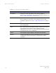
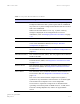
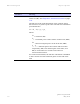
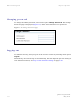
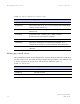
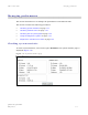

Table Of Contents
- PTP 250 User Guide
- Copyrights
- Safety and regulatory information
- Contents
- List of Figures
- List of Tables
- About This User Guide
- Chapter 1 Product description
- Chapter 2 Planning considerations
- Chapter 3 Legal information
- Chapter 4 Reference information
- Chapter 5 Installation
- Chapter 6 Configuration and alignment
- Chapter 7 Operation
- Chapter 8 Troubleshooting
- Testing link end hardware
- Testing when PoE LEDs do not illuminate correctly
- Testing after a lightning strike
- Test flowcharts
- AC LED is off
- AC LED is flashing
- PORT LED is off
- PORT LED is flashing
- Test Ethernet packet errors reported by ODU
- Test Ethernet packet errors reported by managed switch or router
- Test ping packet loss
- Test resistance at the PoE end of the drop cable
- Testing the radio link
- Testing link end hardware
- Glossary

PTP 250 User Guide Web-based management
phn-2182_002v000
May 2011
7-9
The two ODUs are arranged in a master and slave relationship. The roles of the units
in this relationship are displayed in the page title. The master unit will always have the
title ‘- Master’, and the slave will always have ‘- Slave’ appended to the ‘Systems
Status’ page title.
The status page attributes are defined in Table 7-3
, Table 7-4 and Table 7-5.
Table 7-3 System Status Equipment attributes
Attribute Meaning
Hardware Model Hardware model of this unit.
Version The version of firmware installed. The format of the
attributes is
250-xx-yy
where:
xx
is system release,
yy
minor system release.
Serial Number Serial number of this unit.
Country The country in which this unit is configured to operate. This
is set at first login, as described in Logging into the web
interf
ace on page 6-6. This
can only be reset by restoring the
unit to factory default configuration, as described in
Resetting to default configuration (with country reset) on
pag
e 7-26.
System Name Name of this PTP 250 system. This is set in the Installation
Wizard; see Step 2: Wireless configuration on
page 6-17.
End Location Location of this link end. This is set in the Installation Wizard;
see Step 2: Wireless configuration on page 6-17.
Model Number Model number of this unit.
Connectorized ‘Yes’ means that the unit is connectorized.
‘No’ means that the unit is integrated.
System Uptime The time (days and hh:mm:ss) that has elapsed since the last
system reboot.
The system can reboot for several reasons, for example,
commanded reboot from the Reboot PTP 250 webpage, or a
power cycle of the equipment.