
User's Manual


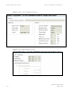
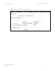
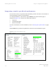
Table Of Contents
- PTP 250 User Guide
- Copyrights
- Safety and regulatory information
- Contents
- List of Figures
- List of Tables
- About This User Guide
- Chapter 1 Product description
- Chapter 2 Planning considerations
- Chapter 3 Legal information
- Chapter 4 Reference information
- Chapter 5 Installation
- Chapter 6 Configuration and alignment
- Chapter 7 Operation
- Chapter 8 Troubleshooting
- Testing link end hardware
- Testing when PoE LEDs do not illuminate correctly
- Testing after a lightning strike
- Test flowcharts
- AC LED is off
- AC LED is flashing
- PORT LED is off
- PORT LED is flashing
- Test Ethernet packet errors reported by ODU
- Test Ethernet packet errors reported by managed switch or router
- Test ping packet loss
- Test resistance at the PoE end of the drop cable
- Testing the radio link
- Testing link end hardware
- Glossary

PTP 250 User Guide Connecting link to the network
phn-2182_002v000
May 2011
6-31
Connecting link to the network
When antenna alignment is complete, the link performance must be checked and then
the link connected to the network for operational running.
This task consists of the following procedures:
• Reviewing system configuration attributes on p
age 6-31
• Comparing actual to predicted performance on
page 6-34
• Connecting to the network on page
6-35
Reviewing system configuration attributes
Review the system configuration to check that it is correct for operational running. To
do this, select the following menu options:
• Configuration (Figure 6-22).
• Configuration, LA
N Configuration (Figure 6-23).
• Configuration, Date/Time (Figure 6-24).
If any s
ettings are incorrect, return to the installation wizard and update the
configuration as described in Using the installation wizard on
page 6-14.