
User's Manual


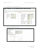
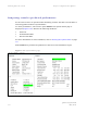
Table Of Contents
- PTP 250 User Guide
- Copyrights
- Safety and regulatory information
- Contents
- List of Figures
- List of Tables
- About This User Guide
- Chapter 1 Product description
- Chapter 2 Planning considerations
- Chapter 3 Legal information
- Chapter 4 Reference information
- Chapter 5 Installation
- Chapter 6 Configuration and alignment
- Chapter 7 Operation
- Chapter 8 Troubleshooting
- Testing link end hardware
- Testing when PoE LEDs do not illuminate correctly
- Testing after a lightning strike
- Test flowcharts
- AC LED is off
- AC LED is flashing
- PORT LED is off
- PORT LED is flashing
- Test Ethernet packet errors reported by ODU
- Test Ethernet packet errors reported by managed switch or router
- Test ping packet loss
- Test resistance at the PoE end of the drop cable
- Testing the radio link
- Testing link end hardware
- Glossary

PTP 250 User Guide Aligning antennas
phn-2182_002v000
May 2011
6-27
Aligning separate antennas for spatial diversity
If a connectorized ODU is installed at either site with two separate antennas for spatial
diversity, proceed as follows:
1
Connect the horizontal polarization antenna to the ODU, disconnect the
vertical polarization antenna, and then perform Aligning antennas on
page
6-25.
2
Connect the vertical polarization antenna to the ODU, disconnect the
horizontal polarization antenna, and then perform Aligning antennas on
pag
e 6-25.
3
Re-connect the horizontal polarization antennas. The received signal level
should increase.
4
Weatherproof the antenna connections at the ‘H’ and ‘V’ interfaces of the
ODUs, as described in Mounting and connecting antennas on
page 5-9.
Monitoring received signal level
The goal of antenna alignment is to find the center of the main beam. This is done by
adjusting the antennas while monitoring the receive signal level. Choose one of two
methods for monitoring receive signal level:
• Antenna alignment tones on pag
e 6-28
• Graphical alignment on
page 6-29