
User's Manual
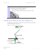
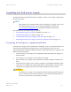
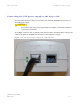


Table Of Contents
- PTP 250 User Guide
- Copyrights
- Safety and regulatory information
- Contents
- List of Figures
- List of Tables
- About This User Guide
- Chapter 1 Product description
- Chapter 2 Planning considerations
- Chapter 3 Legal information
- Chapter 4 Reference information
- Chapter 5 Installation
- Chapter 6 Configuration and alignment
- Chapter 7 Operation
- Chapter 8 Troubleshooting
- Testing link end hardware
- Testing when PoE LEDs do not illuminate correctly
- Testing after a lightning strike
- Test flowcharts
- AC LED is off
- AC LED is flashing
- PORT LED is off
- PORT LED is flashing
- Test Ethernet packet errors reported by ODU
- Test Ethernet packet errors reported by managed switch or router
- Test ping packet loss
- Test resistance at the PoE end of the drop cable
- Testing the radio link
- Testing link end hardware
- Glossary

PTP 250 User Guide Connecting to the unit
phn-2182_002v000
May 2011
6-3
Connecting to the unit
Perform this task to connect a management PC to the unit, power it up and open the
web interface.
This task consists of the following procedures:
• Configuring the management PC on
page 6-3
• Connecting to the PC and powering up on
page 6-5
• Logging into the web interface on
page 6-6
Configuring the management PC
NOTE
Install Java on the management PC (if not already installed), as this is used
by the PTP 250 web interface.
To configure the local management PC to communicate with the PTP 250, proceed as
follows:
1
Select Properties for the Ethernet port.
2
Select the Internet Protocol (TCP/IP) item as shown in Figure 6-1.
3
Click on Properties.
4
Enter an IP address that is valid for the 169.254.X.X network, avoiding:
169.254.0.0 and 169.254.1.1 and 169.254.1.2
A good example is 169.254.1.3 (Figure 6-2).
5
Enter a subnet mask of 255.255.0.0.
Leave the default gateway blank.