
User's Guide Part 2


User Guide: PTP 600 Series Installing E1 and T1
phn-0896_009v003
Feb 2010
UNDER DEVELOPMENT
5-51
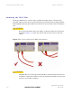
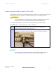
Figure 5-20 Cable connection diagram (T568B color coding)
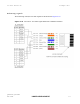
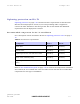
Table 5-2 Telecoms connection pin out
Telecoms Connector Pinout Signal Name
Pin 1 E1T1A_TX-
Pin 2
E1T1A_TX+
Pin 3
E1T1A_RX-
Pin 4
E1T1B_TX-
Pin 5
E1T1B_TX+
Pin 6
E1T1A_RX+
Pin 7
E1T1B_RX-
Pin 8
E1T1B_RX+
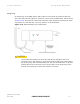
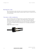
Connections at the ODU and patch panel
The E1/T1 connections at the ODU and patch panel are illustrated in Figure 5-21.