
User's Guide Part 2


Installing E1 and T1 Chapter 5 Installation
phn-0896_009v003
5-50
UNDER DEVELOPMENT
Feb 2010
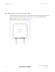
Installing E1 and T1
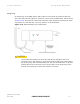
This section describes the installation and configuration of the E1/T1 interface.
NOTE
The maximum cable length between the ODU and the customers terminating
equipment is 200m (656 feet) for E1/T1.
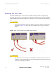
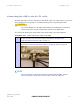
E1/T1 connection diagrams
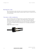
The E1/T1 cable should be assembled as described in Cables and connectors on page
1-15. This p
rocedure applies to the ODU termination, but it must be repeated for the
customer equipment end of the cable when the cable is terminated with an RJ45.
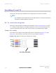
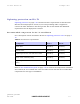
T568B color coding
The T568B color coding used in RJ45 E1/T1 cables is illustrated in Figure 5-19 and
Figure 5-20.
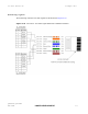
The telecoms connection pin outs are specified in Table 5-2.
Figure 5-19 RJ45 pin connection (T568B color coding)