
User's Guide Part 2


Installing the GPS receiver for PTP-SYNC Chapter 5 Installation
phn-0896_009v003
5-32
UNDER DEVELOPMENT
Feb 2010
3
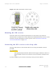
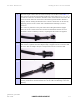
Connect the socket contacts using either of the following techniques:
Crimp
Crimp the socket contacts onto each of the conductors using the correct crimp
tool and positioner, setting the wire size selector to ‘3’ for 24AWG wire.
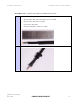
Solder
When soldering the socket contacts onto each of the conductors, ensure that
there is no solder or flux residue on the outside of the contact. Care should also
be taken that the individual conductor insulation does not peel back with the
soldering heat, allowing possible shorts when assembled into the connector shell.
4
Fit four contacts into the unused locations, to provide strength and sealing.
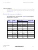
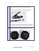
Pin insert side: Connector mating side: