
User's Guide Part 2


Test link end hardware Chapter 7 Troubleshooting
phn-0896_009v003
7-2
UNDER DEVELOPMENT
Feb 2010
Test link end hardware
Before testing link end hardware, confirm that all outdoor drop cables, that is those
that connect the ODU or GPS receiver (if installed) to equipment inside the building,
are of the supported Superior Essex cable type, as defined in Outdoor connections on
page 1-15.
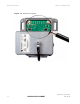
W
hen the link end hardware (PIDU Plus, LPU, ODU and cabling) has been installed,
test it by following this procedure:
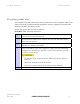
Procedure 7-2 Testing link end hardware
1
Apply mains or battery power to the PIDU Plus. The green Power LED should
illuminate continuously.
2
After 45 seconds, the orange Ethernet LED should be observed starting with
10 slow flashes.
3
Connect the CAT5e cable from the LAN port of the PIDU Plus to the network.
The Ethernet LED should blink randomly as traffic passes through.
4
If the Power and Ethernet LEDs do not illuminate correctly, test the link end
as described in the flowchart (
Figure 7-1) and detailed test procedures that
follow.
5
If a UltraSync GPS synchronization unit has been installed, but one or more of
its status LEDs are not illuminated, refer to Test UltraSync GPS receiver on
page
7-16.