
User's Guide Part 2


Installation pages Chapter 6 Operation
phn-0896_009v003
6-58
UNDER DEVELOPMENT
Feb 2010
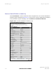
Channel A Line Code
The line code setting of the telecoms interface. This must match the setting of the
device connected to this interface.
Channel B Line Code
The line code setting of the telecoms interface. This must match the setting of the
device connected to this interface.
NOTE
If a copper loopback is used to test the E1/T1 link, ensure that the test set is
configured manually. If the test set is allowed to configure automatically, neither
it nor the ODU send a signal until they receive one, so the test appears to fail.
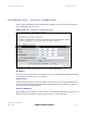
Channel A/B Cable Length
This field is applicable to the T1 operating mode only. It configures the T1 transceiver
to output a signal suitable for driving a cable of the specified length. This should be
set to reflect the length of cable between the wireless unit and the connected
equipment.
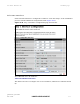
Lowest Telecoms Modulation Mode
The lowest modulation mode at which telecoms data will be sent, if there is sufficient
link capacity.
In conjunction with the LINKPlanner tool, this setting may be used to optimize the
latency for links which operate in consistently high modulation modes. High data rate
links are able to support lower latencies.
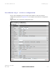
The lowest telecoms modulation mode is selected from a rate ordered drop-down list.
If this selected mode has insufficient capacity to support the telecoms data then the
effective lowest modulation mode, determined when the wireless link starts, will be
higher. The effective lowest modulation mode is displayed on the Telecoms
Configuration page.