
User's Guide Part 1


User Guide: PTP 600 Series Wireless operation
phn-0896_009v003
Feb 2010
UNDER DEVELOPMENT
1-31
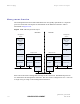
PTP-SYNC front panel
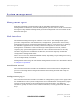
The PTP-SYNC front panel is illustrated in Figure 1-15. The annotated interfaces are
described in Table 1-6.
Fi
gure 1-15 PTP-SYNC front panel
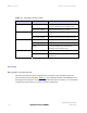
Table 1-6 PTP-SYNC front panel interfaces
Number Description Function
1 GPS/SYNC IN Input from GPS receiver module.
2 SYNC OUT Output to cascaded GPS-SYNC units.
3 USB Input for software upgrades. Contact Motorola for instructions.
4 1PPS IN Coaxial alternative to GPS/SYNC IN. Peak input suppy must
not exceed 5V.
5 LED bank
LEDs and their functions are described in
Table 1-7.
6 PIDU IN Input from PIDU.
7 ODU Output to ODU.
8 Ground stud For connecting to a ground point.