
User's Guide Part 1


PIDU Plus PTP 300/500/600 Series Chapter 1 Product description
phn-0896_009v003
1-10
UNDER DEVELOPMENT
Feb 2010
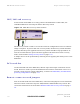
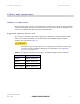
ODU, LAN and recovery
At the bottom of the PIDU is an entry point for the PIDU Plus to ODU cable, the
1000BaseT Ethernet network port and the Recovery switch.
Figure 1-5 PIDU Plus recovery switch location
The Recovery switch is used to recover the unit from configuration errors or software
image corruption. To put an ODU into recovery mode, the Recovery switch should be
pressed, then the power applied. The Recovery switch should be kept pressed for at
least 20 seconds after the power has been applied. Full instruction on the recovery
mode can be found in Using recovery mode on
page 7-20.
A simple reboot can be performed by removing and re-applying the mains power to the
PIDU Plus.
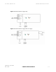
DC In and Out
On the left hand side of the PIDU Plus, 48V DC input and output connections can be
found. These are used to power the PTP 600 Series from an external DC source or to
provide a level of power supply redundancy, as shown in Redundancy and alternative
po
wering configurations on page 1-11.
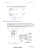
Remote connectors and jumpers
Also on the left hand side of the PIDU Plus, connectors and jumpers can be found that
allow the remote connection of power LED, Ethernet LED and Recovery switch. The
connection instructions can be found in Remote LEDs and recovery switch on p
age 1-
14 .